Arduino DigitalRead using Push Button
Hello friends! Welcome back to ElectroDuino. This is the Arduino Tutorial #8 – Arduino DigitalRead using Push Button. After understanding LED Brightness Control Using Potentiometer in the Arduino Tutorial #7. In this blog, we going to describe What is Push Button Switch, How to Use Push Button Switch with Arduino, Arduino Push Button DigitalRead Code/sketch, and Circuit Diagram.
What is Push Button Switch
The Push-Buttons are the most common switch which we see in our daily life electronic equipment. Push-Buttons are normally-open tactile switches. When we pressed the button it makes the circuit connect and when released the button it makes the circuit connection break. We can see from the outside this switch consists of four terminals. but both side of the terminal is internally connected.
How to use Push Button Switch with Arduino
If we connect the push button switch directly to Arduino to get digital input, It means switch one pin is connected to Ground or 5v Vcc, and another pin is connected to Arduino digital pin. In this case, the Arduino is read unstable input from the push button.
So, we need to connect a “pull-up” or “pull-down” resistor circuit to stabilize the input, when using the switch.
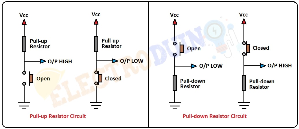
Pull-up Resistors
If the push button one pin is connected to the Vcc through a resistor and the other pin is connected to the ground, this circuit is known as the pull-up resistor circuit. In this case, the push button output is High(1) when the button is open, and the output of the push button is Low(0) when the button is pressed.
Pull-down Resistor
If the push button one pin is connected to the ground through a resistor and the other pin is connected to the Vcc, this circuit is known as the pull-down resistor circuit. In this case, the push button output is Low(0) when the button is open, and the output of the push button is High(1) when the button is pressed.
Arduino DigitalRead
At first, we need to connect the pull-down or pull-up resistor circuit’s output pin to Arduino digital pin, to read the output data from the push button. The output of the push button is the connection point of the push button and the resistor.
To read this output from the push button we must do two things in Arduino code. The first one is to set the Arduino digital pin as an INPUT mode and another one is used digitalRead( ) function to read the input value. When the Arduino digital pin gets 5v as input, it read HIGH or 1 and the Arduino digital pin gets 0v or ground as input, it read LOW or 0.
Arduino Push Button DigitalRead
In this tutorial, we use a pull-down resistor circuit to read digital data from the Push button switch and print the output on the serial monitor of the Arduino IDE software.
Components Required
| Components Name | Quantity |
| Arduino Uno | 1 |
| USB cable for Arduino Uno | 1 |
| Push-button switch | 1 |
| 10k Resistor | 1 |
| Connecting wire | As required in the circuit diagram |
Arduino Push Button DigitalRead Circuit diagram / Schematic
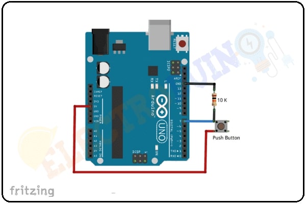
Circuit Wiring
| Components Pins | Arduino Pins |
| Push Button switch terminal 1 | +5 v Vcc |
| Push Button switch terminal 2 | connected to Arduino GND pin through a 10K ohm resistor |
| The output pin is the switch and resistor connection point. | Digital pin ” D7 “ |
Arduino Push Button DigitalRead Code/sketch
/*
Arduino Tutorial #8 - Arduino Push Button DigitalRead.
http://www.electroduino.com
*/

int pushButton = 7;

void setup()
{
 Serial.begin(9600);
 pinMode(pushButton, INPUT);
}

void loop()
{
 int buttonState = digitalRead(pushButton);
 Serial.println(buttonState);
 delay(1);
}
Code Analysis
Here we will describe the code line by line for your better understanding.
| Code Line | Description |
int pushButton = 7; |
It is declared your switch output pin is connected to Arduino pin “D7” and named as pushButton. |
Serial.begin(9600); |
This function is used to begin serial communication, at 9600 bits of data per second, between your Arduino board and your computer. |
pinMode(pushButton, INPUT); |
Set the Arduino digital pin 7 as an INPUT, to read the output from the push button switch. |
int buttonState = digitalRead(pushButton); |
This is the main function in the loop of the program. It read digital output (0 or 1) from the switch and stores the value in the variable |
Serial.println(buttonState); |
Finally, this command is used to print the switch output value on the serial monitor window. |
delay(1); |
wait for 1 millisecond to see the result clearly. |
Output Result
you can see your output value on your serial monitor window. when you pressed the switch then the output is “1” and when you released the switch then the output is “0”.