Ultrasonic Sensor Module HC-SR04 Datasheet | How it Works
Hello friends! Welcome back to ElectroDuino. This blog is based on What is Ultrasonic Sensor or HC-SR04 module | How it Works. Here we will discuss Introduction to Ultrasonic Sensor or HC-SR04 module, Pin Diagram, Working Principle, Features, applications, and Datasheet Pdf Download.
Introduction to Ultrasonic Sensor or HC-SR04 module
The Ultrasonic HC-SR04 Sensor Module is a very popular sensor, it is used in many applications where measuring distance and detecting objects are required. Its works on the same principle as a radar system. Ultrasonic sensors work by emitting high-frequency sound waves, that is not heard by humans. It sends out a high-frequency sound pulse from the transmitter and then the receiver receives this sound when it reflects back from any object surface. This way the sensors detect objects. It can measure distance or detect objects in the range of 2cm-400cm. The is comfortable with both microcontroller and microprocessor platforms like Arduino, ARM, PIC, Raspberry Pie, etc.
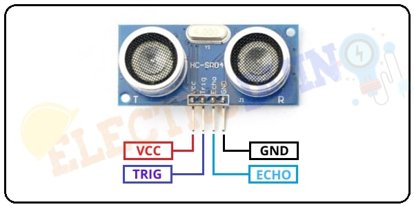
Ultrasonic Sensor Pin Diagram / Pinout

| Pin No | Pin Name | Description |
| 1 | Vcc | This is the power supply pin of the sensor, input voltage +5 V DC. |
2 | Trig | The trigger pin works as an input pin. This Trig pin has to be kept high for 10 µs to sending ultrasonic waves from the Transmitter part. |
3 | Echo | The echo pin works as an output pin. This pin produces a pulse when the reflected signal is received. The length of the pulse is equal to the time it took for the transmitted signal to be detected. |
4 | Ground | This is the Ground pin of the sensor, which is connected to the ground pin of the DC supply. |
| You Should Know: Interfacing Ultrasonic Sensor with Arduino |
How Ultrasonic Sensor Module Works
The ultrasonic sensor working principle is the same as like object detection system of a bat. Also, we can say that it works on the same principle as a radar system. The ultrasonic or HC-SR04 module has two main parts, one is the Transmitter (TX) and, another one is Receiver(RX). The transmitter sends Ultrasonic (US) sound and the Receiver receive the US sound.

First of all, we need to set the Trig pin on a High State for 10 µs (microseconds) to generate the ultrasonic sound. Then it will send out an 8-cycle sonic burst which will travel at the same speed of sound. If the 8-cycle waves fall on any object and it bounces back from the object surface, then it’s collected by the receiver part of the module. As a result, The ultrasonic sensor echo pin produces a high pulse output. The output pulse duration is the same as the time difference between transmitted ultrasonic bursts and the received echo signal.

s = (v x t)/2
Where, s is the distance between the sensor and object. v is the speed of sound in Air, v = 0.034cm/µs or 340 m/s . t is the time sound waves take to bounce back from the object’s surface. We need to divide the distance value by 2 because time will be double as the waves travel and bounce back from the initial point.
Specifications
| Parameter | Value |
| Main Parts | Transmitter & Receiver |
| Operating Voltage | 5 V |
| Operating Current | <15mA |
| Operating Frequency | 4 MHz |
| Measuring angle covered | <15° |
| Measuring Distance (Theoretical) | 2cm to 400cm |
| Measuring Distance (Practical) | 2cm to 100cm |
| Accuracy | absolute error ~0.035 cm/cm. |
| Sensor Dimensions | 45mm x 20mm x 15mm |
Applications
- Used to measure the distance.
- obstacles detection.
- Used in robotics to avoid and detect obstacles
- map the objects surrounding the sensor by rotating it.


