GSM Based Fire Alert System with Text Message & Buzzer Indication
Hello friends! Welcome back to ElectroDuino. This blog is based on GSM Based Fire Alert System using Arduino and SIM800 GSM Module. Here we will discuss Introduction to GSM Based Fire Alert System, Project Concept, Block Diagram, Components Required, Circuit diagram, Working Principle, and Arduino Code.
Introduction
Every day, we hear of fire accidents happening somewhere. It takes the lives of many people and damages huge property. Most of the damages in fire accidents occur due to a lack of early fire detection, it is a very big problem. So, here we will try to solve this problem with the help of smart technology. In this project, we will learn how to make a GSM Based Smart Fire Alert System, which alerts us when the fire started. This system alerts us by sending a text message/SMS to a specific user’s Mobile number and generates sound to warn the people who are present at the accident spot. This system can save many lives and protect from property damage. We can use this system at the office, building, bank, school, factory, shopping mall, etc. places.
Project Concept of GSM Based Fire Alert System
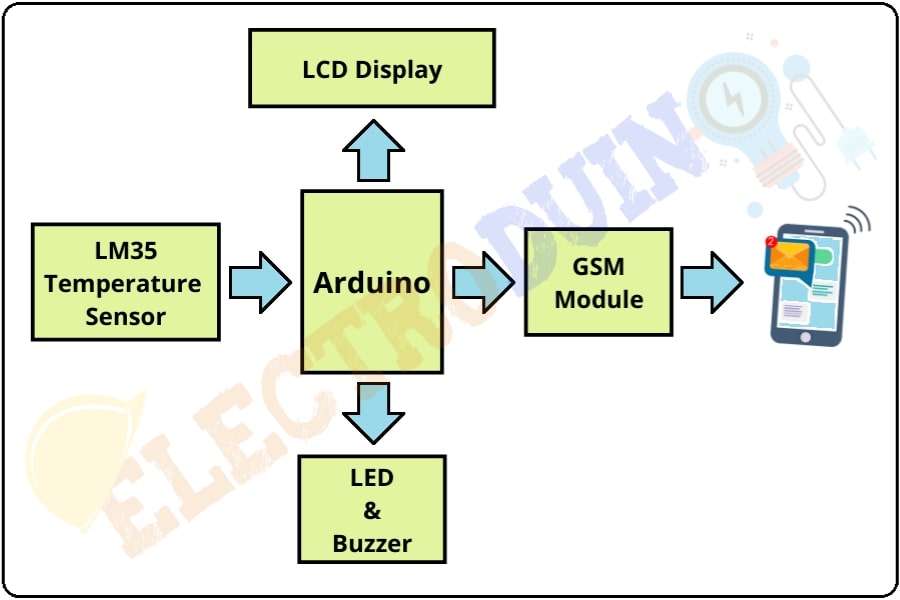
This GSM Based Fire Alert System project concept is very simple and it’s very easy to build. The main components of this project are the LM35 Temperature Sensor, Arduino, SIM800L GSM Module, LCD Display, LED, and Buzzer.
The LM35 is a Temperature Sensor IC, its output voltage change according to the change of temperature around it. Here it is used to measure the temperature of surroundings. When a fire accident occurs, then it detects high temperature and provides a high output voltage. This output voltage goes to the Arduino. Here we will use Arduino NANO which is the main microcontroller of this project, it controls the whole system. The Arduino calculates the temperature using the sensor output. When the Arduino detects more than normal temperature, then it sends commands to the GSM module for sending a Text Message/SMS to a specific user’s Mobile number. The LED and Buzzer are working as a fire indicators. We can see the temperature on the LCD Display.
Block Diagram of GSM Based Fire Alert System

Components Required
| Components Name | Quantity |
| Arduino Nano | 1 |
| LM35 Temperature Sensor | 1 |
| SIM800L GSM Module | 1 |
| 16×2 LCD Display Module | 1 |
| Red LED (D1) | 1 |
| Green LED (D1) | 1 |
| Buzzer (B1) | 1 |
| 1000µf 50V Capacitor | 1 |
| Slide Switch (SW1) | 1 |
| 9V Battery with Battery connector | 1 |
| 4.1 v Power Supply | 1 |
| PCB Zero board | 1 |
| Connecting wires | As required in the circuit diagram |
Tools Required
| Tools Name | Quantity |
| Soldering Iron | 1 |
| Soldering wire | 1 |
| Soldering flux | 1 |
| Soldering stand | 1 |
| Multimeter | 1 |
| Desoldering pump | 1 |
| Wirecutter | 1 |
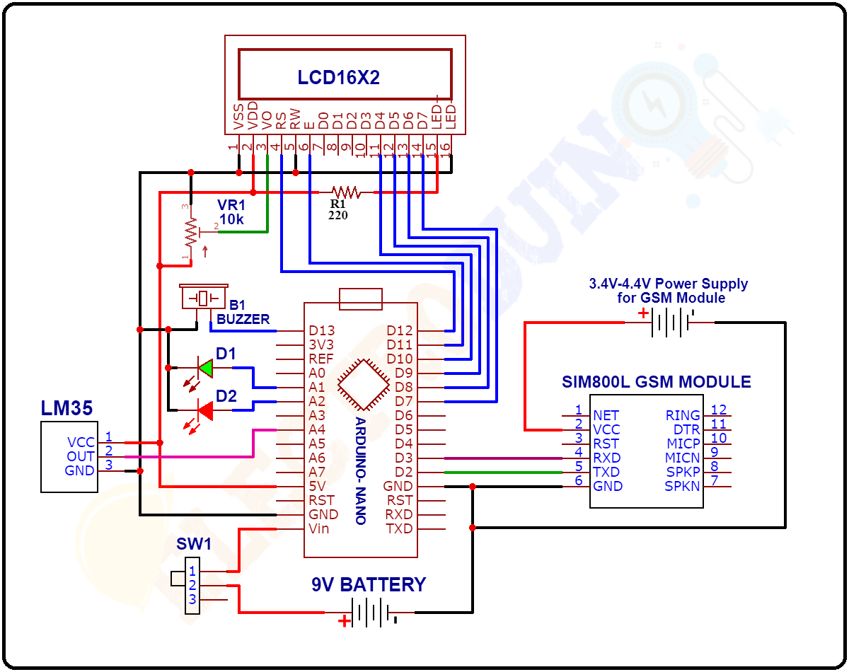
Circuit Diagram of GSM Based Fire Alert System

| Note: SIM800L GSM Module operate on 3.7v-4.4v Power supply. 5v power supply can be destroy the module. So here we are using an 4.1v 2A power supply, which ideal for the module. |
| For more details: SIM800l GSM Module |
Working Principle of GSM Based Fire Alert System
After connecting all components according to the circuit diagram and uploading the code to the Arduino board, now turn on the circuit power supply. Then the Arduino starts working step by step according to the code.
In the beginning, the Arduino makes the connection to the Network through the SIM800L GSM Module. At the same time, the LM35 temperature sensor starts to sense the temperature around it and generates analog output voltage. Its output voltage change according to the change of temperature. The Arduino read this voltage and calculates the temperature in Degrees Celsius (°C) by the following formula which is used in Arduino code.
Temperature = [{(output voltage * 5.0) / 1024}*100.0] °C
When a fire accident occurs, then the room temperature is also increased. Due to this, the output voltage of the LM35 Temperature sensor is also increasing. The Arduino reads this output voltage and calculates the room temperature.
When the room temperature is cross 55°C then the Arduino sends a “Fire Alert!!” message to a particular phone number through the GSM module (you can change the message text and phone number in Arduino code). At the same time, the Red LED and buzzer also turn on, these warn people inside the room and the fire alert message also print on the LCD Display.
During the normal condition the room temperature is less than 50°C then the Arduino detects there is no fire. This time the Green LED will be turned on and the “No Fire! Safe Now” message print on the LCD Display.
Arduino Code
#include <SoftwareSerial.h> //Include Library for GSM Module
#include<LiquidCrystal.h> //Include Library for LCD Display Module
LiquidCrystal lcd(12, 11, 10, 9, 8, 7); //Select Arduino pins for LCD Display
SoftwareSerial mySerial(3, 2);//Arduino's (rx,tx)
int Tempsensor = A4; // LM35 Sensor pin
int RedLED = A2; // Red LED pin
int GreenLED = A3; // Green LED pin
int buzzer = 13; // Buzzer Pin
//Variables for Fire functions
float temp_read,temperatureC, Temp_alert_val,Fire_shut_val;
int Fire_sms_count=0,Fire_Set;
void setup()
{
//Set pin modes
pinMode(Tempsensor,INPUT);
pinMode(RedLED, OUTPUT);
pinMode(GreenLED, OUTPUT);
pinMode(buzzer, OUTPUT);
lcd.begin(16,2);
Serial.begin(9600); // Set Baud rate for serial communication
mySerial.begin(9600); // Sim Baud rate
Serial.println("Initializing...");
delay(1000);
mySerial.println("AT"); //Once the handshake test is successful, it will back to OK
updateSerial();
digitalWrite(RedLED, LOW); // Red LED off
digitalWrite(GreenLED, HIGH); // Green LED on
digitalWrite(buzzer, LOW); // Buzzer off
//Print message on LCD Display
lcd.setCursor(0,0);
lcd.print(" ELECTRODUINO ");
lcd.setCursor(0,1);
lcd.print("Fire Alert System");
delay(2000);
lcd.clear();
}
void loop()
{
CheckFire(); //Check Fire or not
CheckNoFire(); //Check again if Fire stopped
}
// Function to Detect Fire
void CheckFire()
{
// Print message and tempareture value on LCD Display
lcd.setCursor(0,0);
lcd.print(" Fire Scan - ON ");
Temp_alert_val=CheckTemp();
Serial.println(Temp_alert_val);
//When tempareture greater than 55 degree celsius
if (Temp_alert_val > 55)
{
FireAlert(); // Function to send SMS Alerts
}
}
float CheckTemp()
{
temp_read = analogRead(Tempsensor); // reads the Temp sensor Pin output
temperatureC = ((temp_read * 5.0) / 1024)*100.0; // Calculate temperature value in degree celsius
return temperatureC; // returns temperature value in degree celsius
}
// Function to send SMS Alerts
void FireAlert()
{
// Print message on LCD Display
lcd.setCursor(0,1);
lcd.print(" Fire Alert!! ");
digitalWrite(RedLED, HIGH); // Red LED on
digitalWrite(GreenLED, LOW);// Green LED off
digitalWrite(buzzer, HIGH); // Buzzer on
while (Fire_sms_count < 2) //Number of SMS Alerts to be sent
{
mySerial.println("AT+CMGF=1"); // Configuring TEXT mode
updateSerial();
mySerial.println("AT+CMGS=\"+ZZxxxxxxxxxxx\"");//change ZZ with country code and xxxxxxxxxxx with phone number to sms
updateSerial();
mySerial.print(" Fire Alert !! Fire Alert !! "); //text content
updateSerial();
mySerial.write(26);
Fire_sms_count++;
}
Fire_Set = 1;
// Print message on LCD Display
lcd.setCursor(0,1);
lcd.print(" Fire Alert!! ");
// Print message on Serial monitor window
Serial.println("Fire Alert! SMS Sent!");
delay(10);
}
void CheckNoFire()
{
if (Fire_Set == 1)
{
Fire_shut_val=CheckTemp();
//When tempareture less than 50 degree celsius
if (Fire_shut_val < 50)
{
// Print message on LCD Display
lcd.setCursor(0,1);
lcd.print("No Fire!Safe Now");
delay(10);
Serial.println("No Fire");
digitalWrite(RedLED, LOW); // LED off
digitalWrite(GreenLED, HIGH);// Green LED on
digitalWrite(buzzer, LOW); // Buzzer off
Fire_sms_count = 0; //Reset count for next alert triggers
Fire_Set=0;
}
}
}
void updateSerial()
{
delay(500);
while (Serial.available())
{
mySerial.write(Serial.read());//Forward what Serial received to Software Serial Port
}
while(mySerial.available())
{
Serial.write(mySerial.read());//Forward what Software Serial received to Serial Port
}
}


